Deep Learning for Computer Vision · Stanford CS231N
MMVO: Visual-Inertial 3D Reconstruction in Challenging Industrial Environments
Making feed-forward 3D reconstruction survive construction sites: an IMU side network that corrects camera pose, and a diffusion refiner that sharpens depth — without fine-tuning the backbone or using LiDAR at inference.
Motivation
Digital twins of active construction sites depend on an accurate reconstruction of site geometry, yet construction sites are hostile terrain for modern feed-forward reconstruction models. VGGT — a state-of-the-art transformer that jointly infers camera parameters, depth maps, point maps, and 2D tracks in a single forward pass — was trained on scenes that look nothing like an underground level: faint illumination, repetitive surfaces, grayscale imagery, and an absence of clear visual landmarks. Under these conditions the model cannot register correspondences across views, and both its camera poses and its depth maps degrade badly.
Our hypothesis was that inertial measurements could serve as a prior where image features are uninformative on their own. Crucially, we constrained ourselves to interventions that require no fine-tuning of the backbone on new images and no LiDAR at inference time. We therefore decoupled reconstruction into two subproblems — camera pose and depth — and designed a separate intervention for each.
Data and ground truth
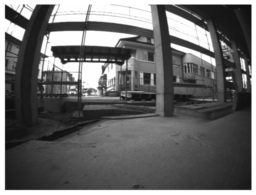
Experiments use the Hilti SLAM Challenge 2023 platform: five synchronized fisheye cameras (720×540, 10 Hz) giving near-omnidirectional coverage, a co-mounted 6-DOF IMU at 200 Hz, and a 32-channel LiDAR at 10 Hz, recorded on real construction sites across floors, underground levels, and staircases.
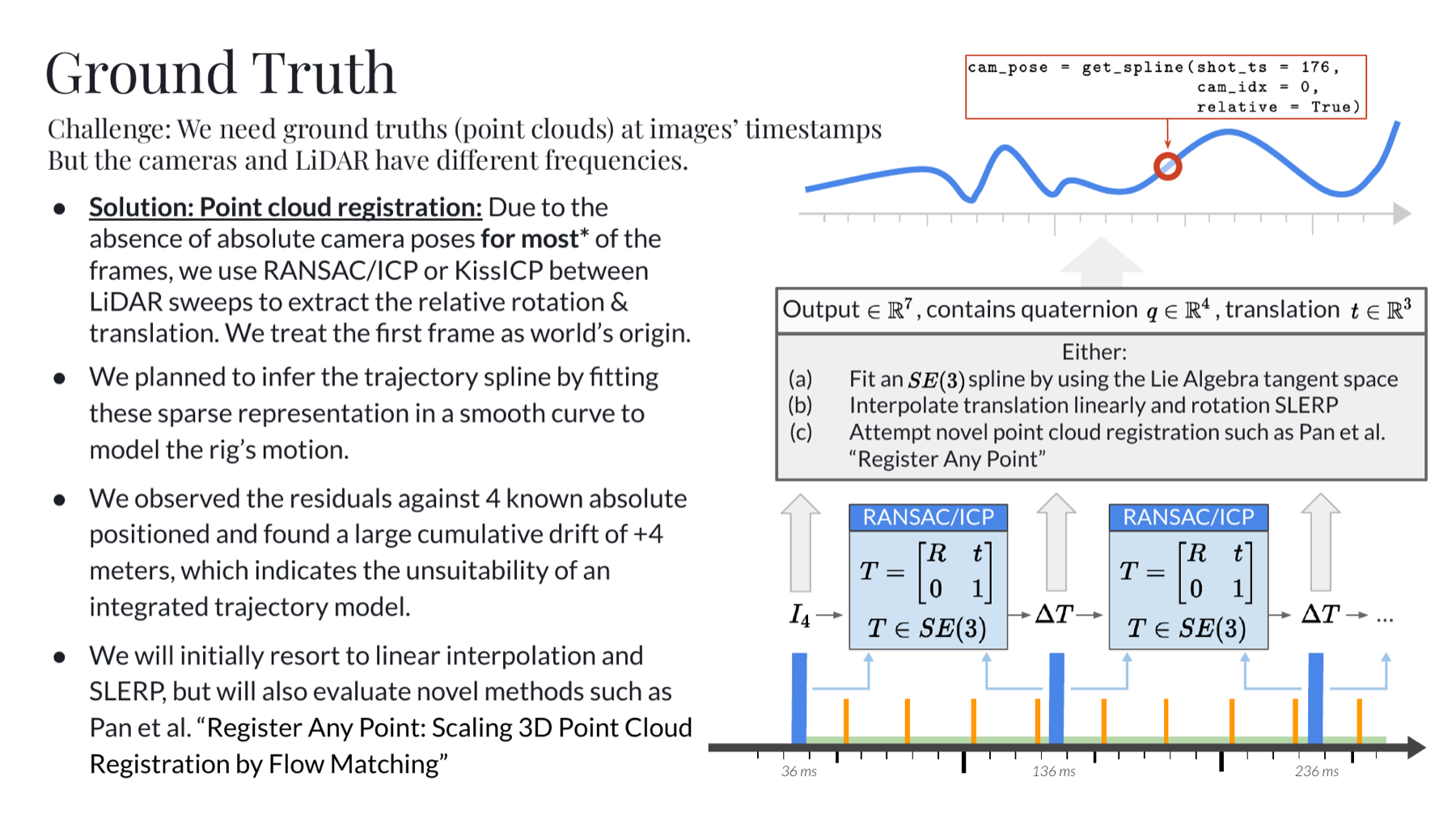
Because the dataset provides no absolute camera poses for most frames, ground truth had to be constructed. We recover relative rotation and translation between LiDAR sweeps via point-cloud registration (RANSAC/ICP and KISS-ICP), treat the first frame as the world origin, and interpolate the resulting sparse SE(3) poses to the images’ timestamps — translation linearly, rotation by SLERP. This step turned out to matter: residuals against four known absolute positions revealed roughly 4 m of cumulative drift, and the sparsity of the LiDAR sweeps makes the interpolated trajectory conspicuously linear. Much of what we later observed in the error analysis traces back to the quality of this surrogate rather than to the networks themselves.
Pose: conditioning camera tokens on inertial measurements
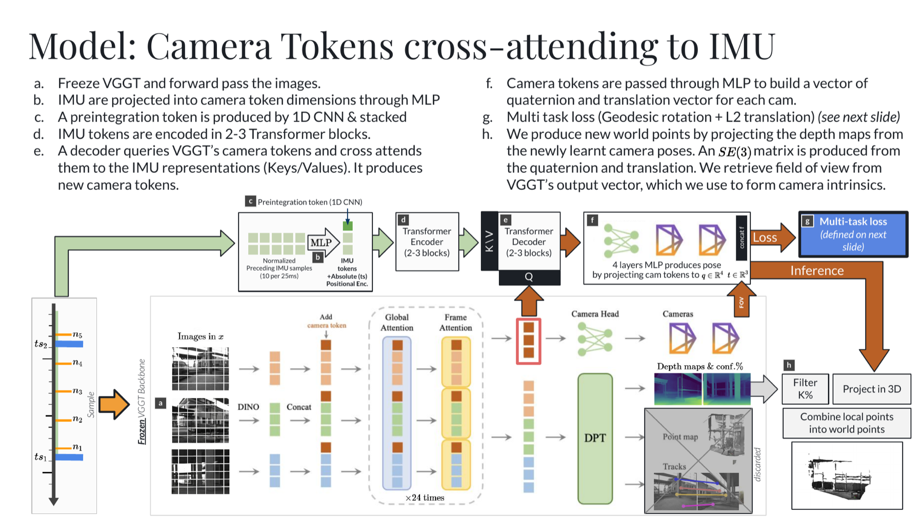
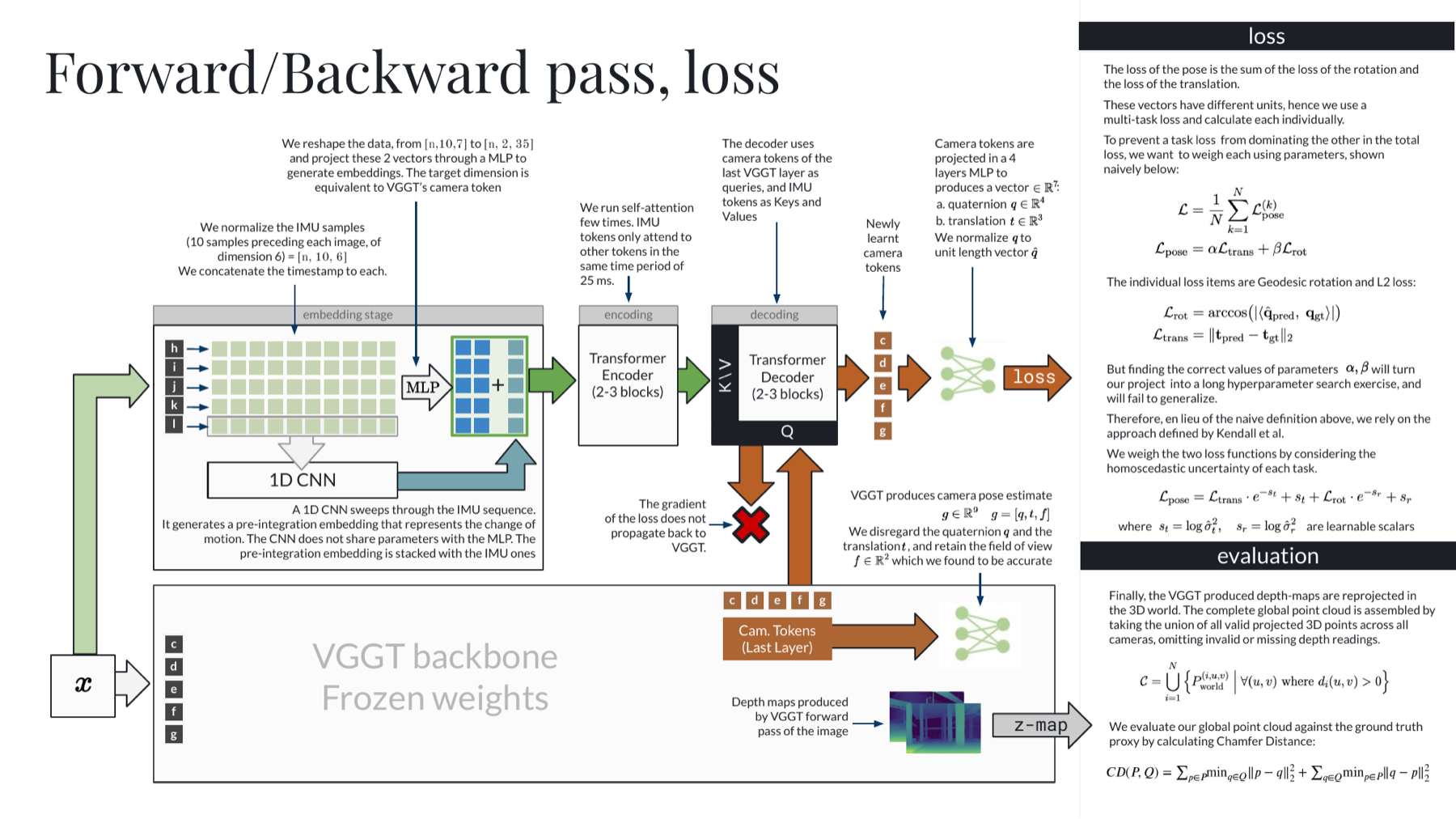
Rather than re-train VGGT, we attach a side network and keep the backbone frozen. IMU readings between consecutive image frames are collapsed into a single relative-motion factor by pre-integration, encoded by a 1-D CNN, projected into camera-token dimensions by an MLP, and passed through two to three transformer encoder blocks. A decoder then takes VGGT’s camera tokens as queries and cross-attends them to the IMU representation as keys and values, producing corrected camera tokens. An MLP head projects these to a quaternion and a translation vector, which we convert to SE(3) for evaluation.
The two objectives — geodesic rotation loss and L2 translation loss — are combined by Kendall’s homoscedastic multi-task weighting, so the network learns how much to trust each task rather than having the balance fixed by hand. No gradient flows back into VGGT.
Depth: a diffusion refiner over coarse predictions
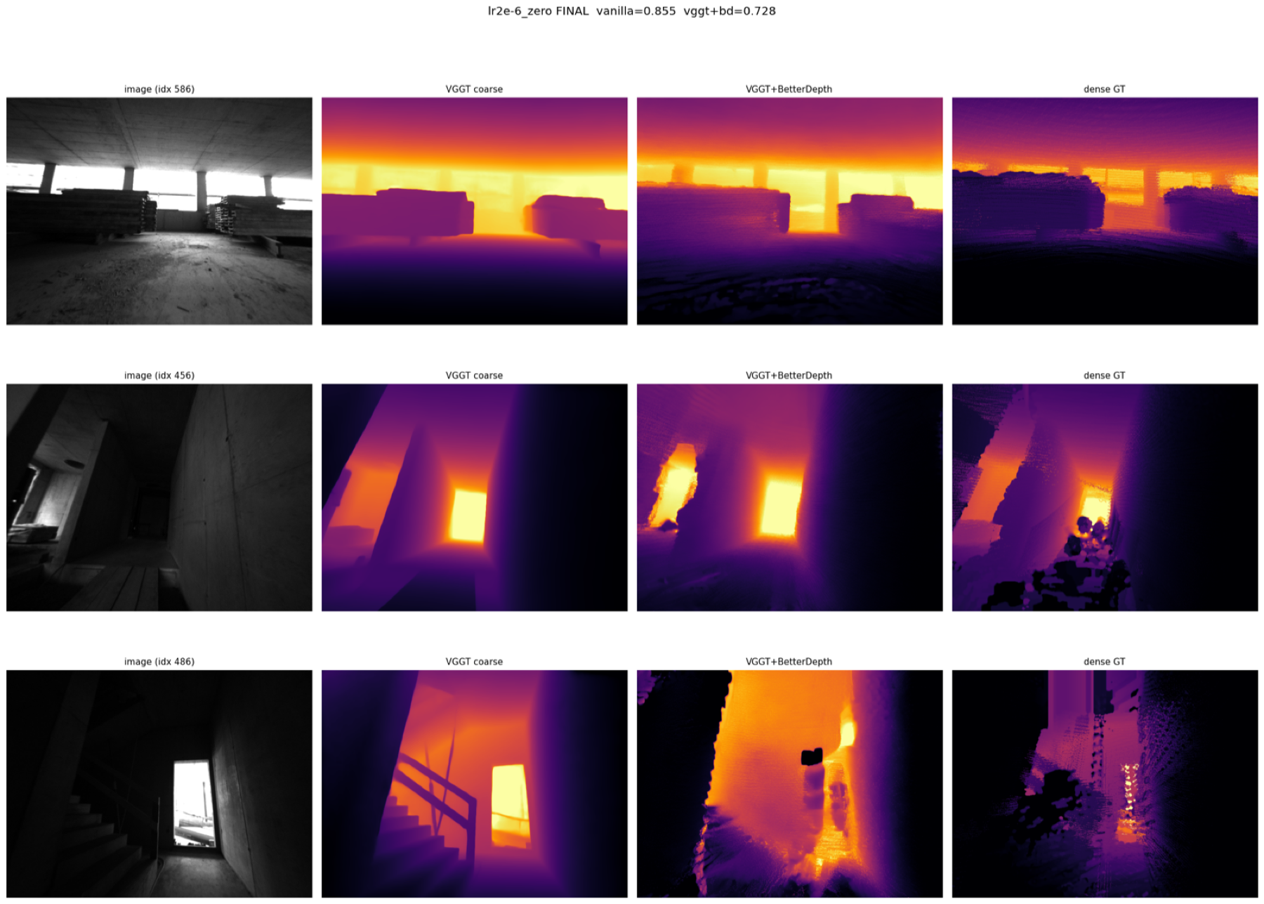
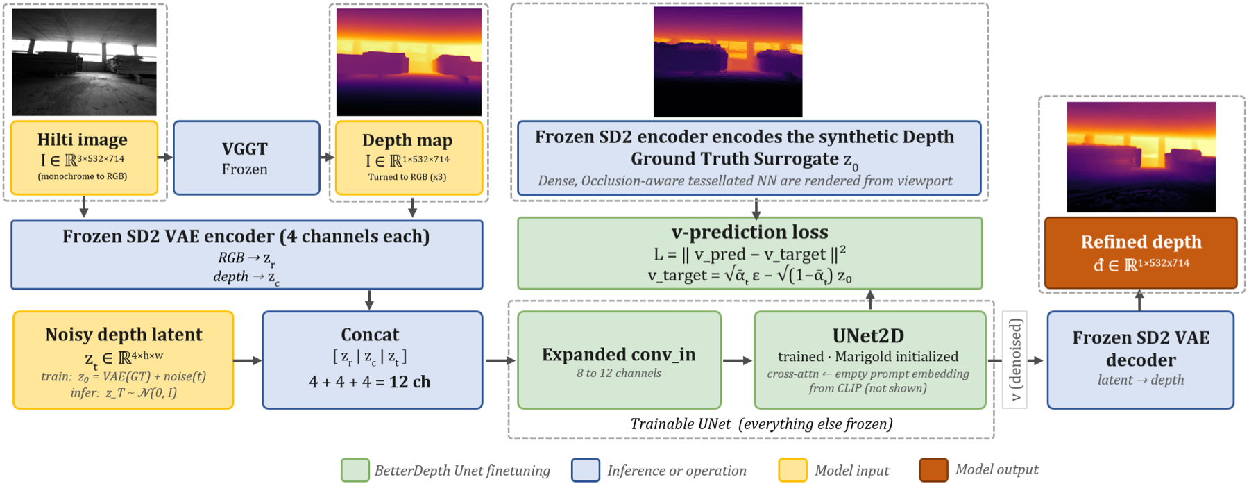
For depth, the frozen VGGT produces a coarse depth map which a BetterDepth-style refiner sharpens through conditional latent diffusion. The Hilti image and the coarse depth map are each encoded by a frozen Stable Diffusion 2 VAE; their latents are concatenated with a noisy depth latent (4 + 4 + 4 = 12 channels) and denoised by a Marigold-initialized UNet trained under a v-prediction objective. Everything except the UNet stays frozen, and a frozen VAE decoder maps the denoised latent back to a refined depth map.
Results
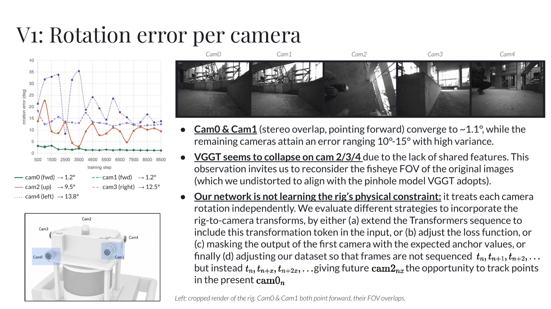
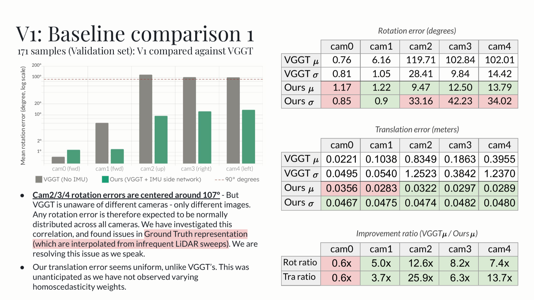
Pose. Conditioning on inertial data removes VGGT’s catastrophic failure on the peripheral cameras. VGGT’s rotation error on cameras 2, 3, and 4 clusters around 107° — an artifact of the fisheye field of view colliding with the pinhole model VGGT assumes, compounded by the near-total absence of features shared between those views. Our network brings these to roughly 9–14°, while relative translation error falls to about 3 cm, well below the 13.2 cm of an IMU-only (VINS-Mono-style) baseline. The improvement in translation is uniform across cameras, unlike VGGT’s, which varies sharply.
The honest caveat is that the VINS-Mono baseline still attains a lower mean relative rotation error — 1.7° against our 7.6°. We attribute this to the injection point of our intervention rather than to the inertial signal itself: the network treats each camera’s rotation independently and never sees the rig’s physical constraint that the five cameras are rigidly co-mounted. Cameras 0 and 1, whose fields of view overlap, converge to about 1.1°; the peripheral cameras, which share little, do not.
Depth. The diffusion refiner lowers per-frame Chamfer L2 from VGGT’s 0.98 m² to 0.75 m². We report this as promising rather than conclusive: the dense ground truth is itself synthesized from sparse LiDAR, and its residual artifacts bound how far the refiner can be trusted.
Documents
The project was developed across three milestones, each of which is available in full:
- Milestone 1 — problem motivation, hypothesis, the Hilti dataset and evaluation protocol, and a review of related work (VGGT, VINS-Mono, LiDAR-VGGT).
- Milestone 2 — ground-truth construction by point-cloud registration, the fusion architecture, the multi-task loss, and the forward/backward pass.
- Milestone 3 — training runs, the per-camera error decomposition, baseline comparisons, and qualitative trajectory analysis.
The final paper, Visual-Inertial 3D Reconstruction in Challenging Industrial Environments, is available as a PDF.